In 2016 I bought and set up the emonPI Raspberry PI-based home energy monitor, which lets me trend and track energy consumption at home.
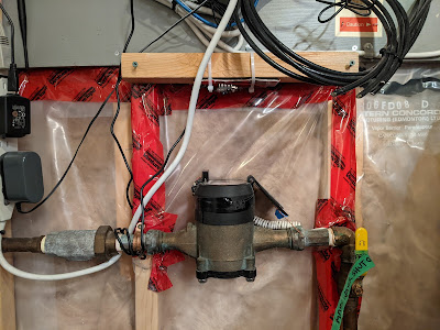
Since then I've wanted to track water and gas usage, but until now I could not find any good solutions (within my abilities). We have an Elster C700 water meter but I was wary of tapping into the built-in digital encoder due to a tamper mechanism (this sentence also overstates my ability and ambition... I like solutions that someone else has pioneered first).
This post is about deploying jomjol's AI-on-the-edge-device project to an ESP32-CAM module in order to get my analog water meter back into Home Assistant for monitoring, trending, and alarming. The audience is interested geeks and ESP32 beginners attempting to deploy this project for the first time. I'm going to expand on jomjol's instructions and talk about some of the mistakes I made along the way. I will also describe the kludgey, roundabout way I integrated data via MQTT back into Home Assistant.
Results first:
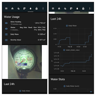 |
| Home Assistant integration done! |
Lots more details "after the jump".
OK. Again, target audience is interested geeks and beginners. This was my first ESP32 project, so I'm going to take jomjol's Installation and Configuration instructions and expand on them, and talk about some mistakes that I made.
Parts and materials needed. I've included some links to the stuff I got.
- ESP32-CAM with the OV2640 camera module and 4M PSRAM (these specs are important)
- A Micro SD card (16 GB or smaller)
- USB Micro-B breakout board to power the ESP32
- USB Micro-B power supply (from your junk drawer, or buy a new one)
- A USB-to-Micro SD card reader (like this)
- A USB to UART interface, also known as USB to TTL 4-wire. I got this one
- Other stuff that will be useful:
- A solderless prototype board and different jumper wires. I had bought this kit previously which had everything I needed
- A soldering iron for the Micro-B USB breakout board
- Whatever materials you might need to install your ESP32-CAM board in your home. jomjol has a great 3D printed solution on the Installation page; you will see mine is much more... homemade
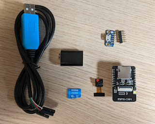 |
| Here are most of the key parts |
What I'll do in this section is quote pieces of jomjol's Installation page, and add a few more notes and lessons-learned and mistakes I made. For clarity, I'll use italics for the quotes, and all quotes were taken 2022-02-20 so they may have been updated in the meantime.
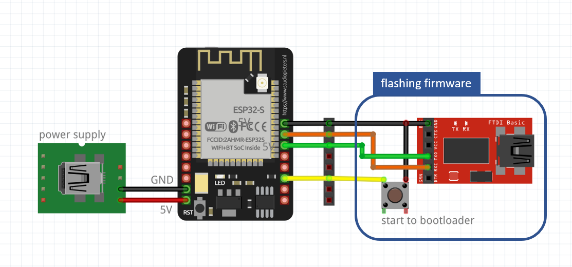
Wiring
Beside the 5V power supply, only for the first flashing a connection to the USB-UART connector, including a short cut of GPIO0 to GND for bootloader start.
A example for wiring can be found here:
The first thing I did was solder some pins onto the Micro-USB breakout board. This will make it easy to power the ESP32.
 |
| Top: Soldered. Bottom: Unsoldered. |
The next step is assembling the everything per the wiring diagram above. This is made much easier and less messy if you have a solderless breakout board. Here is a simplification: you do not need the button. Simply wire GPIO0 (where the yellow wire lands on the above schematic) directly to GND, and when you power everything on the ESP32-CAM goes to bootloader (programming-friendly mode).
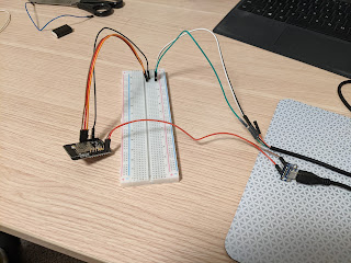 |
| My setup for ESP32-CAM programming |
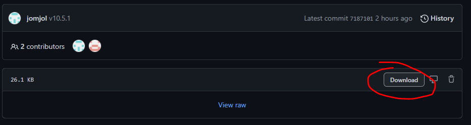
The next thing you need to do is download the ESP32 bootloader, firmware, and partitions .bin files from Github. Let me save you a LOT of time and heartache if you don't use Github all the time, you need to know how to download these files properly. If you go to this firmware page and right-click, download the 3 files, you'll get .bin files but they'll be wrong and filled with Github HTML headers.
To download these properly, you need to click ON the files (circled):
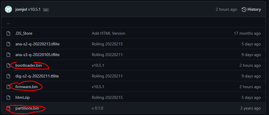
THEN you click the download button:
I spent wayyyy too long troubleshooting my USB-serial communication at the end of a long workday, ending my day with an email to the developer asking for help. The next day I realized my error and sent an embarrassed follow-up message. Don't repeat this bone-headed mistake!
OK, let's take a look at the firmware flashing instructions.
1. Using esptool in python directly
For this you need a python environment (e.g. Anaconda in Win10). Here you need to install the esptool:
pip install esptool
Then connect the ESP32 with the USB-UART connector to the system, put it in bootmode and with the following command you can erase the flash and flash bootloader, partitions and firmware in two steps:
esptool erase_flashesptool write_flash 0x01000 bootloader.bin 0x08000 partitions.bin 0x10000 firmware.bin
Maybe you need to specify the COM-port if it is not detected by default.
My suggestion is to follow Method 1 (esptool in python) instead of Method 2 (Using the Flash Tool from Espressif). I had started with Method 2 because it seemed easier, but the lack of command line diagnostic messages prevented me from seeing the dumb error I'd made above (downloading the wrong .bin files).
You'll need Python 3 on your computer. I'm assuming you're on Windows. Grab the latest release here and follow the installer instructions. It's been a while since I did this, but be sure to complete the part about setting up Python PATH variables so you can run Python in any folder.
Next, install PIP. There are instructions here, or just Google "install pip for Windows".
Now open a Command Prompt and type py to see if you've installed Python correctly. Type exit() to get out of the Python shell.
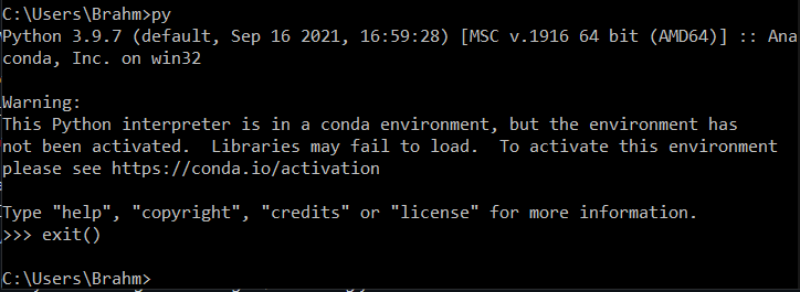
Now type the pip install esptool command. This will install the tools for communicating with your ESP32-CAM.
We are now ready to flash the ESP32-CAM! Ensure it is powered up in bootleader mode, connected to your computer via the USB-UART interface. It will be worth checking Device Manager to see if you have the right drivers for the USB-UART interface. You should see a COM device in Device Manager.
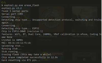
Type esptool.py.exe erase_flash - note the difference from the instructions above. My experience was without the .py.exe, I got a message like this:
You should see something like this happening:
If you don't see the above, here are some troubleshooting ideas:
- Ensure you have a serial device shown in Device Manager
- Check all of your wiring, and double-check it.
- Check that your Python environment is functional.
- Check that esptool is properly installed.
- Reboot your ESP32-CAM (unplug the power and plug it back in - this fixed one issue for me)
- Pay attention to the error messages and use Google.
Now we're ready to write the .bin firmware files. To do this, you need to navigate in your command prompt to the folder the .bin files are stored in. In the screenshot below, you can see I'm in C:\Users\Bra
hm\Desktop. Enter the command esptool.py.exe write_flash 0x01000 bootloader.bin 0x08000 partitions.bin 0x10000 firmware.bin - noting the "py.exe" addition.
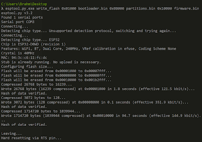
The screenshot above clearly shows data successful transfer to the ESP32. During my first attempt, which was using the Espressif tool, the unclear interface made troubleshooting very hard.
Power down the ESP32-CAM for a moment because it's time to prep the micro SD card.
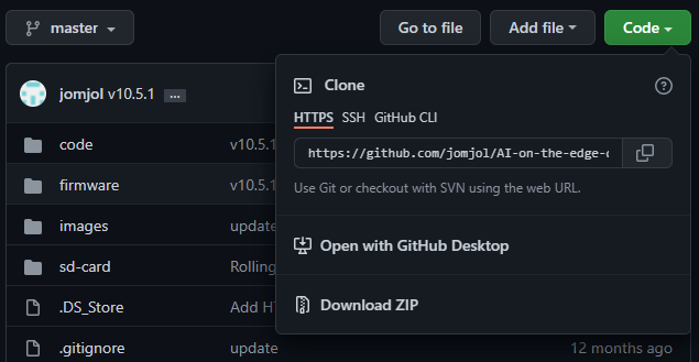
SD-CardAgain here's where I'm embarrassed about my lack of git and Github knowledge. If you follow the link in the instructions, there's no clear way to just download the files. So, go to the project homepage, click the green Code drop-down, and Download ZIP of the whole project.
The program expects a SD-Card installed with certain directory and file structure in order to work properly. For the first setup make a copy of the SD-Card subdirectory to the root of the sd-card.
Now:
- Format your micro SD card per the instructions: single partition, FAT32, 32k.
- Copy the contents of the sd-card directory from the project download to the SD card.
- Open up wlan.ini which should be located in the root of the SD card:
- Enter a wifi SSID between the quote marks. Note it must be a 2.4 GHz network, not 5 GHz.
- Enter the wifi password.
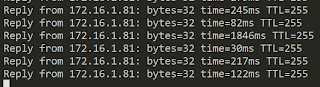
- Note on static IPs. If you enter one, remove the semicolons from the start of the line. You don't need zeroes padding the IP (this is unclear from the example given: "123.456.789.012"). For example I entered "172.16.1.81" as my static device IP without any padding zeros.
Give it a few minutes on first boot before connecting to the web interface.
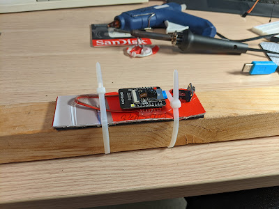
In the meantime, figure out how you're going to physically install this thing. My kludgey way: hot-glue the ESP32-CAM to a piece of cardboard, the same dimensions as a 2x2" board. Use 2 zip-ties to fix the cardboard to the board, tight enough to stay in place, but loose enough to adjust if needed.
Before physically installing for good, we need to ensure the camera has a good focal length.
Configuration
Open a web browser and connect to the IP or hostname you configured in wlan.ini.
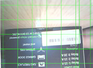
In the initial graphical configuration menu, you can click into the first few steps to start taking test pictures with "Create New Reference". Here's a pic of a box on my desk:
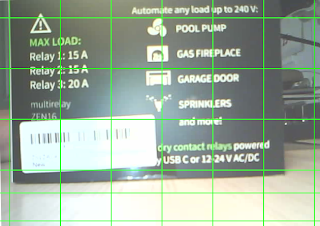
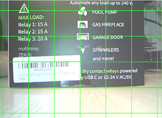
This image was more blurry, so I made a couple more attempts rotating counter-clockwise until I was happy with the sharpness:
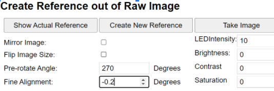
I should also note that the documentation is a little bit unclear about Create New Reference and Take Picture. "Create New Reference" doesn't change the image captured after you've changed LED intensity, brightness, etc. But Take Image will apply the settings. So, use the Take Image button to take your initial pics for calibrating focal length.
 |
| Far less elegant than the 3D printed fitting, but it will work!! |
Now it's time to go through the whole software configuration. I thought the documentation for this was solid, so I am not going to go through all the steps. Be patient and read the instructions!
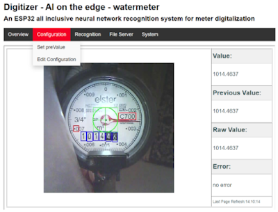
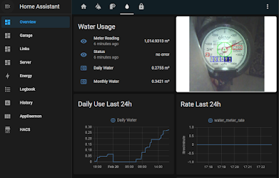
After a lot of testing and tweaking in the configuration, I had a reading!!
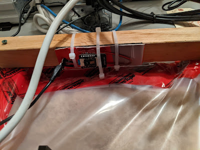 |
| Middle zip tie serves to diffuse LED light. It is on loose |
Configuring MQTT and linking data back to Home Assistant
In the Configuration --> Edit Configuration of the web interface, you can specify an MQTT broker to pump data to. Here is where my setup gets a bit convoluted and where there is probably room for simplification.
You need to be running an MQTT broker, like mosquitto, somewhere. You point AI-on-the-edge-device at the broker, and pull data to Home Assistant via an MQTT add-in, like this:
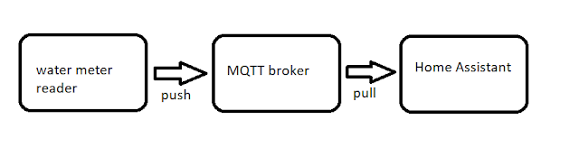
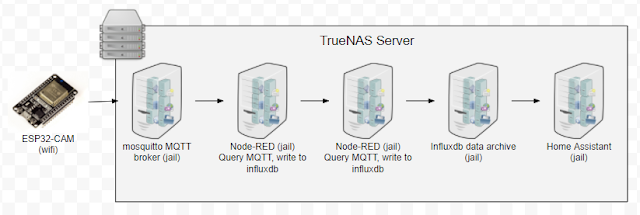
That's it!
- Alarms and alerts for water usage when Robyn & I are away from home
- Tweaking or improving the AI recognition for the analog dial that takes up the whole face of the dial. I found some documentation on it, but haven't gone deep yet. I think a new training model will need to be built which is something I have no idea how to do (yet).
- The time on my ESP32-CAM was stuck in 1970. Issue 654 discusses this, there are some clues in Issue 586. In the config menu on the web interface, enabling "Expert Mode" reveals some time server settings, I used a Canadian pool.ntp.org IP of 194.0.5.123 and the POSIX string "CST6CDT,M3.2.0/2,M11.1.0/2" for time zone. This seemed to fix it!
- The reason why this mattered...I turned on logging of raw images under "MakeImage" in the config.ini file. I want to capture a bunch of raw images to see if I can train a neural network for the dial on my meter. The images did not seem to be logging properly with the time zone set wrong.
Can you share your homeassistant setup on the water meter? Got the water meter running thanks to your excelent guide, but having some issues with homeassistant side.
ReplyDelete